AUTOMATIC VIBRATORY PARTS FEEDER BOWL DRIVE UNIT MAINTENANCE
|
Related Links Full line of part handling systems. Get quotation from a Vibromatic estimating engineer. |
| Vibromatic (Press Release) Are you experiencing problems with your vibratory feeder bowl drive unit? Your options are probably to try and fix it yourself per the proceedures as described below or have a VIBRATORY PARTS HANDLING COMPANY fix it for you. In either case understanding vibratory drive unit terminology and troubleshooting procedures will prove to be quite helpful. |
| Automatic vibratory parts feeder bowls always required some type of vibratory drive unit to power them. All leaf spring type drive units function under similar principals so, the procedures as outlined below will applied to most. If your are in the learning mode, this is a great place to pick up "tricks of the trade". You may want to take a look at the pages on "Vibratory Parts Handling Systems Terminology" and maybe even take the "Vibratory Feeder Bowl" quiz to better understand the terms used in vibratory drive unit tuning procedures. |
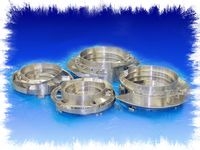
Polycast Vibratory Feeder Bowls |
Stainless Steel Vibratory Feeder Bowls |
|
|
|
|
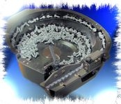
Vibratory bowls are securely attached to the top member of the drive unit. It is very important that the bolts used to secure the vibratory bowl to the drive unit are very tight. When securely tightened the vibratory action of the drive unit is used to power the bowl in either a clockwise or counterclockwise rotation.
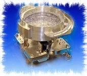
The following procedure may be used to check the tuning of any 60 or 120 HZ base drive unit:
- IMPORTANT! Before tuning unit, make sure there are no cracked or broken springs, that all bolts are
 torqued, and the magnet pole faces are set at the proper gap.
With the variable speed controller on and the proper level of parts in the bowl, set the dial at 35% to 40% of the in-put voltage. Some parts movement should be detected at this point. If the feed rate is too slow, increase the controller setting slowly until the desired feed rate is attained. When 80% of the in-put voltage has been used without reaching the desired amplitude or there is excessive or sporadic vibration, check for interference points where something may be contacting the bowl or base drive unit, then follow these tuning techniques to achieve maximum efficiency:
- Loosen a bolt on any one of the spring clamp blocks (preferably a lower bolt), very gradually, until the unit either speeds up or slows down. If the unit speeds up, it is over sprung. If the unit is over sprung, the thinnest spring from two opposing hangers must be removed. When replacing the springs they must be torqued as specified in "Base Unit Torque Requirements."
If after this change, there is an under sprung reading (if unit slows down when a bolt is loosened), thinner springs must be added back to the two opposing hangers. IMPORTANT! To maintain consistent, even feed motion, the number of springs in opposing spring packs must be equal.
The base unit should be slightly over tuned, but the degree of over tuning must be established. An over tuned condition is a good indication that all bolts are tight and all springs are in good condition.
- Springs tend to work-harden on a base drive unit that has been- in operation for a period of time, causing it to be over tuned. The same procedure as described in (1.) should be used to determine if this condition exists.
- If a unit indicates that it is still under sprung after a spring has been added, check for a spring that may be cracked or broken. This usually happens on the bottom portion of the spring, near the spring clamp hanger. In some cases, the crack cannot be seen because of paint or because it may not be all the way through to the point where it is easily visible it should be removed and inspected closely for hairline cracks.
- Make sure the bolts are long enough to fasten the springs to the spring hangers. For example, if a 5/16" thick spring has been added, there will be 5/16" less of the threads to hold the springs. When tightened, the threads may strip and the unit will give a false tuning reading. The same also applies to the bolts holding the armature or the bowl clamp nuts. The holes for these bolts are blind, therefore if the bolt bottoms out, it will seem to be tight when it actually is not. This situation will cause false readings in the tuning process.
- Another factor that affects tuning is the stretching of the bolts that fasten the springs. We use grade "5" bolts, which are specially hardened for durability to prevent this from occurring.
- The tuning of a base drive unit is affected when a weld is either broken or cracked any place in the drive unit or:
- (a) The mounting flange of the bowl.
- (b) The track or skirts.
- (c) The bottom of the return pan.
- (d) The braces, pan wall, discharge area (as a general rule, these conditions will create a foreign noise and be easily detected).
- Another condition, that occasionally develops and is very difficult to detect, is bolts that hold the rubber feet onto the base drive backing out, causing solid contact between the drive unit and mounting surface. This can cause the tuning to be misread. The way to check for this condition is to remove the unit from the common base plate, and lift it up so that the feet are exposed and tighten the mounting screws.
- It is very important that the clamp nuts holding the bowl to the base drive are tight. When remounting or relocating a bowl on a base drive unit, use a 12" to 15" pipe on 9" to 15" units and one 36" to 48" long for 18" to 36" units. This gives the necessary leverage to tighten the bolts. (For the best results, use a torque wrench). Also, never pull a bowl out, even slightly, from the clamp nuts to line it up with an existing track. Instead, use the jack screws (for leveling and height adjustment) which are built into each LP drive unit as a standard feature. If the bowl is not level, parts may fall off or drift from the track prior to entering a selector causing track jams, misoriented parts and a loss of feed rate. A feeder must be level in order to maintain proper feed motion.
- Another problem can result by omitting the thin shim (spring spacer) between the springs when they are changed or added. These spacer shims are very important. If one is omitted, it will result in an adverse affect on tuning. If a shim is not available, one should be made and installed. Don't take the easy way out and try to get by without it. This will only cause more problems later.
- The feed rate will be affected if all bolts that attach the rubber feet to the mounting plate are not securely located. These bolts are to prevent the unit from rotating on the plate. When the drive unit is securely mounted to the plate, optimum feed motion will be transferred to the vibratory bowl.
Also, make sure that the holes are drilled on center and that the rubber feet are not stretched when tightened. This will prevent tuning problems.
- If the gravity or inline track is connected to the vibratory bowl, the feed motion will be adversely effected. The solution is to use an independent track to move the parts from the bowl discharge.
- If a feeder bowl has "dead spots", most often, the problem can be found by looking 180 degrees from the location of these "dead spots". As a general rule, mass has been added without counter-balancing the bowl, the gap in the coil has been improperly set, there is a broken weld, broken spring, or a loose spring bolt. Any of these conditions may contribute to the problem.
|
www.vibromatic.net/index.htmlVIBROMATIC COMPANY, INC. |
i